Final Project - Pikachu in the House!
Geon Soo Park
Project Concept
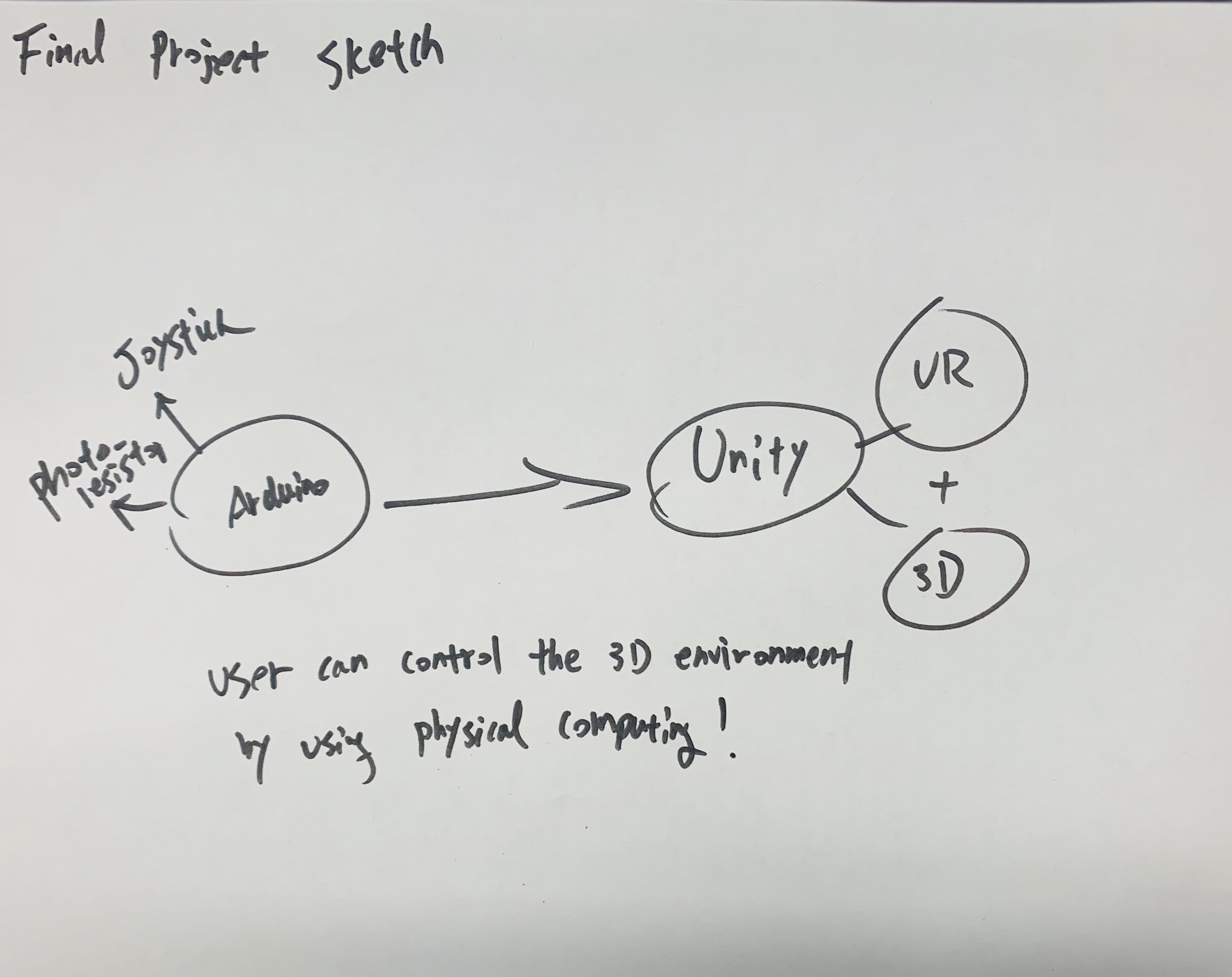
For the final project, my initial goal was to connect physical computing to the virtual environment. Therefore, in the project, the user can interact with objects in the 3D environment (Pikachu) or the virtual environment with physical computing components (ex: joystick and photoresistor).
I give credit to my friend, Lee, for the Pikachu animation.
Demo Video
Techinical Implementation
Schematic
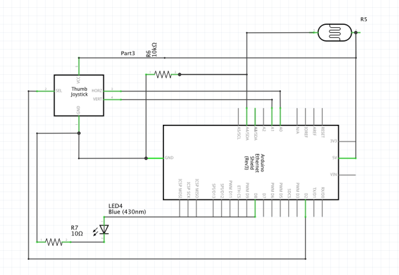
For Schematic I only drew 9 LEDs instead of 30 LEDs; to make the schematic simple
For the blue LED, I used a 10k resistor. The voltage drop for blue LED is 3.3 V and by using the Ohm's Law which is 1.7/0.02 = 85 ohms; 10k resistor would be enough for the blue LED (if the ohms are higher than the resistor then it will overburden the LED. If the resistor is too high, then the flow of electricity is too low). For the photoresistor, I used a 10k resistor. The maximum current allowed to go into the ground pin is 200mA, and I chose 5V for the power. R = V/I = 5v/0.02A = 250a. We need a resistor bigger than 250a. Furthermore, we need to use a resistor divider to allow the high impedance Analog input to measure the voltage. We need to use the formula: Vout=Vin*(R2/(R1+R2)) to find the value for Vout. Vin is the 5V, R2 is 10k ohm, and R1 is the photoresistor (10k ohm). Lastly, for the joystick controller, I did not use any resistors.
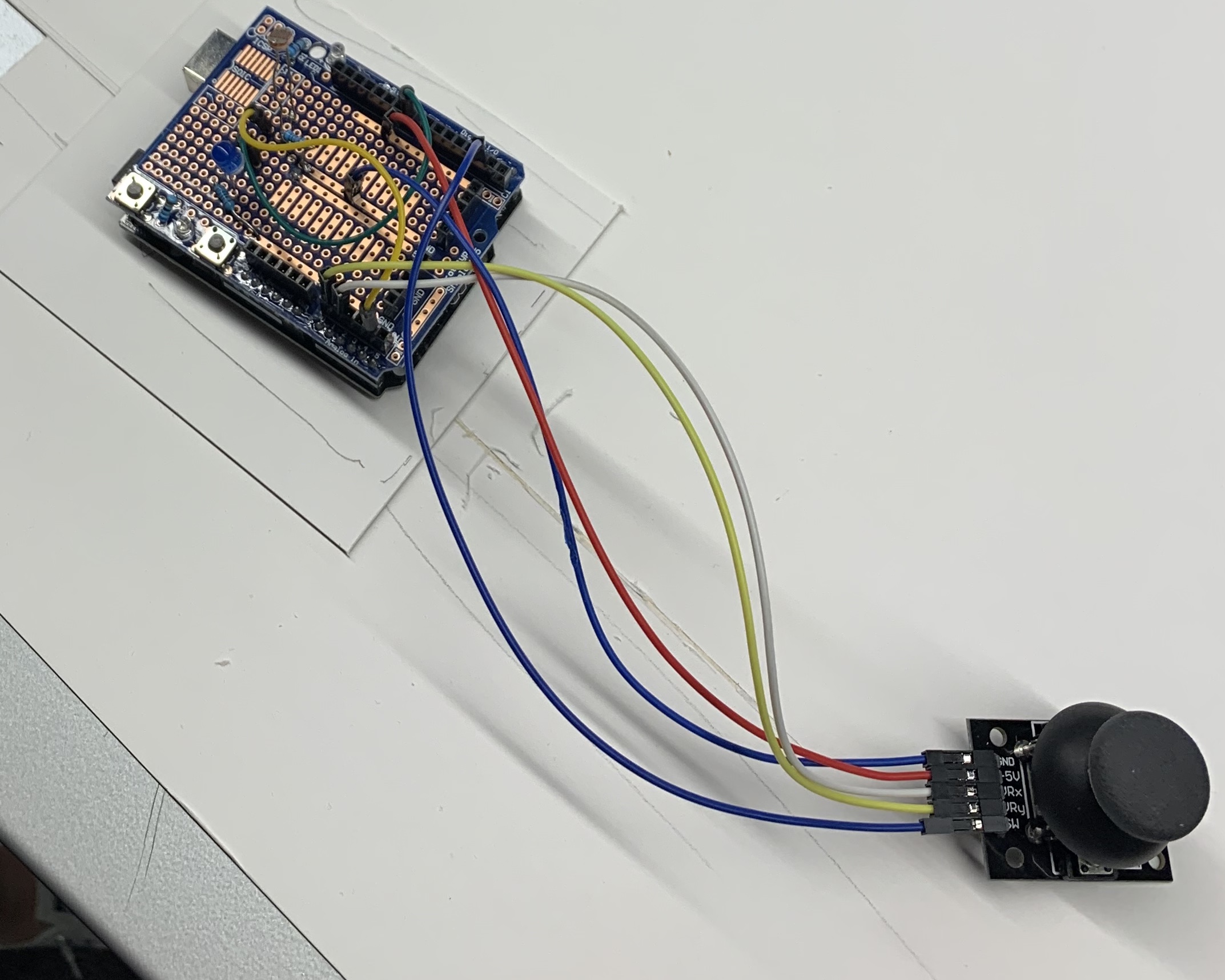
Circuit
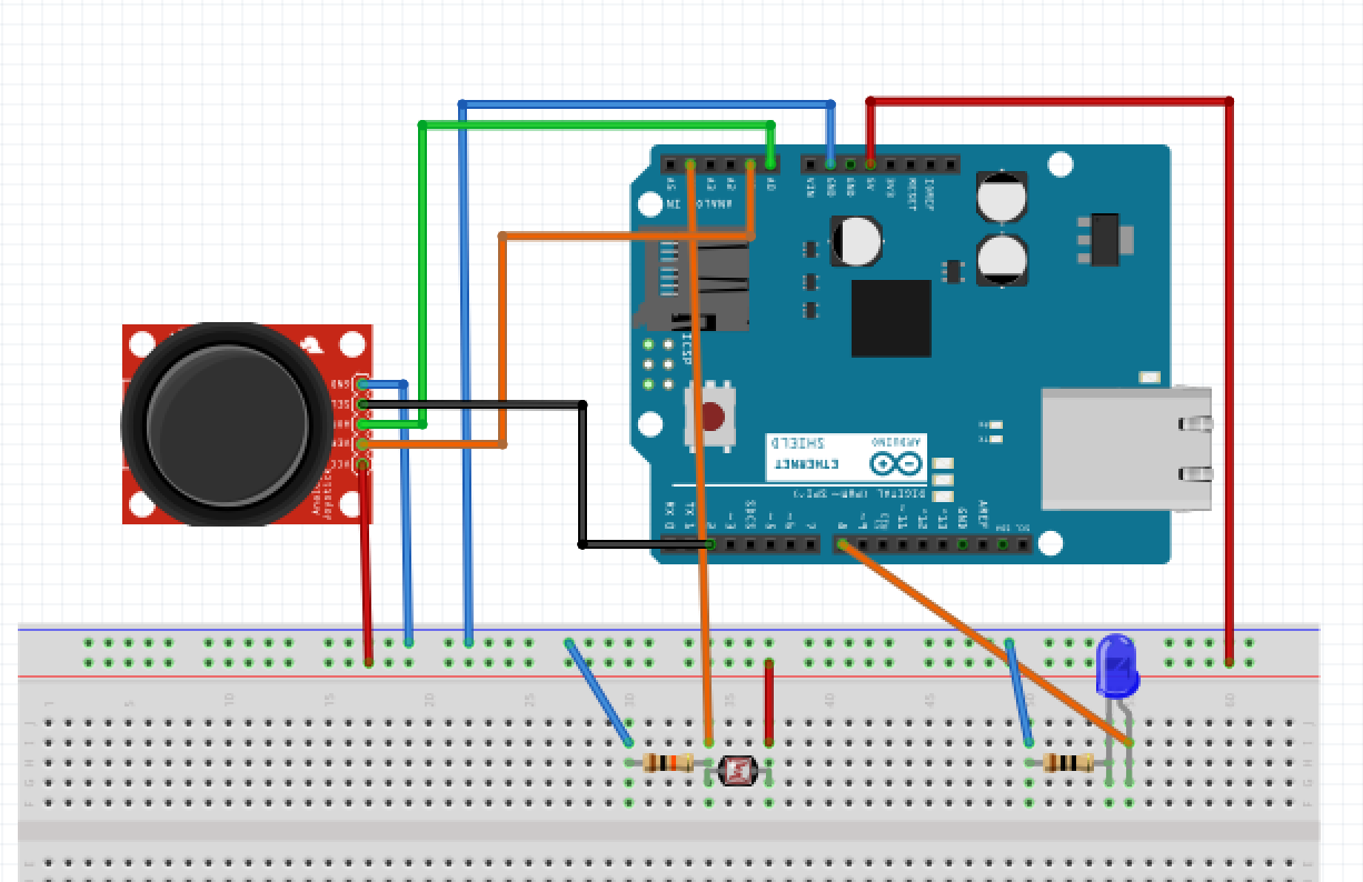
The photoresistor is connected to the 5V and connected to the ground pin through a resistor. It is also connected to pin A4 which functions as a trigger for the input for the photoresistor.
The blue LED is connected to pin 8 through a resistor and connected to the ground pin. Lastly, for the joystick controller: the x-axis is connected to A0, the y-axis is connected to A1, the switch button is connected to pin 2, 5V power, and ground.
Firmware
For my project’s firmware, the most important key is to connect and to send the data from Arduino to Unity. I am sending the data as an array data structure: [0,0,0,0]. In the array, the first value is the x-value, the second one is the value, the third one is the switch button, and the last value in the array is the value from the photoresistor.
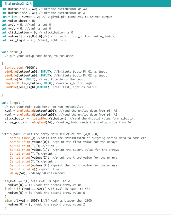
Code 1 - Arduino
First, I initiated all the int values such as Pin number, and x, y, button values. Then, I also created an empty array (int values[] = {0,0,0,0};//{xval, yval, click_button, value_photo};).
There are inputs from the joystick controller (x, y, and switch button) and the photoresistor. There is one output: a blue LED.
In the code, I used the Serial.print and Serial.println to print the arrays (ex: [0,0,0,0].
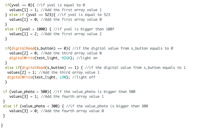
Under that, it is about changing the value for the arrays based on the joystick and the photoresistor. For example: if the analog value for the x-value is equal to 0, then the first value in the array changes to 1. If the value equals the 501, then it changes to 0, and if the analog value is bigger than 1000, then 2. It is similar for the y-value. If the analog value for the y-value is equal to 0, then the first value in the array changes to 1. If the value equals the 523, then it changes to 0, and if the analog value is bigger than 1000, then 2.
For the switch button, if the value is 0, then it adds 0 in the third value of the array and also turns on (digitalWrite) the blue LED. If the value is 1, then it adds 1 in the array and turns off (digitalWrite) the blue LED. Lastly, for the photoresistor, if the analog value from the photoresistor is bigger than 500, then it adds 1 in the 4th value in the array. If the value is less than 300, then it adds 0 in the array.
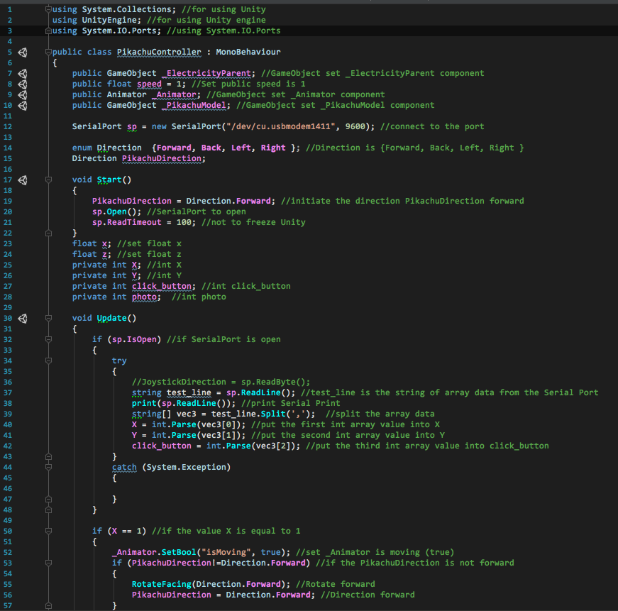
Code 2 - Unity - Movement
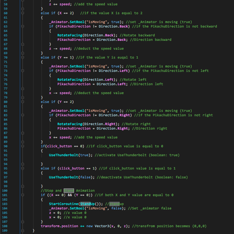
This is a cs code for the Unity, and this code controls the Pikachu. First, put "using System.IO.Ports;" on top of the Unity code and connect to my Arduino port name. Tt will open the SerialPort of my Arduino. Then, by using the ReadLine() function, it will read the array list one by one. By splitting the code using a comma, I can split the array and retrieve an int one by one. Since this code controls the Pikachu model, I only have to use the three values (first: x-value, second: y-value, and switch) from the array. After this, Unity code becomes very similar to the Arduino code. If the x == 1, then it moves the object forward. If the x value is 2, then it moves the object backward. If the y-value is equal to 1, then it moves to the left. If the y-value is equal to 2, then it moves to the right. When both the x and the y-value are 0, then the object does not move. Lastly, if the click button (the switch button) is 0, then it sends the boolean true. If it is true, then it activates the electricity. If it is 1, then it is false and deactivates the electricity.
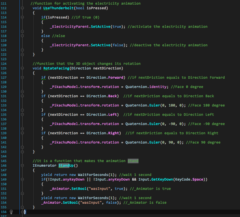
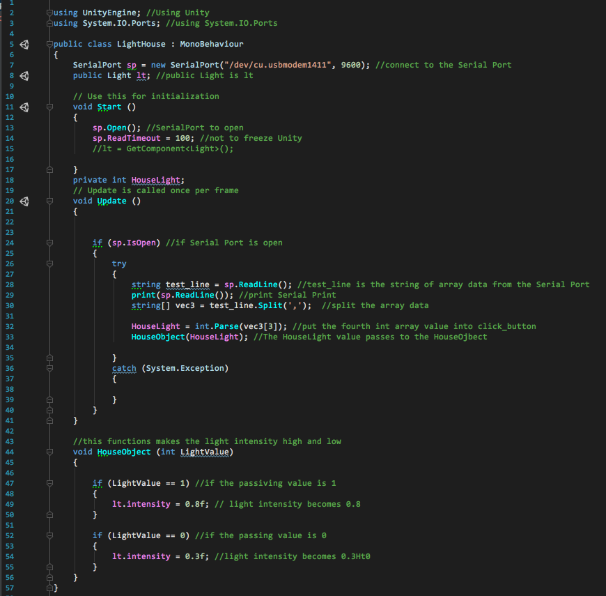
Code 3 - Unity - House Light
This is a cs code for the Unity, and this code controls the light intensity of the Pikachu House. Similar to the Pikachu movement code, it will first open the SerialPort of my Arduino. Then, it reads the array and splits the array by using a comma. Since I only have to get the value for the last value in the array, I parse the last value and put it in the HouseObject. If the HouseObject is 1, then it changes the light intensity to 0.8. If it is 0 then, it changes to 0.3.
Implementation Process and Technical Write Up
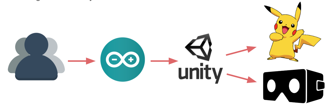
The concept of my project is connecting the physical computing to the virtual environment or the 3D environment. First, you need to make inputs and outputs from your Arduino. Then, you need to send the data from Arduino to Unity. For this part, I used the array data structure. Then, you need to write a code that opens the Unity and parse the array data structure. Afterward, you just send each data to your functions and it will eventually control your Unity.
You can check out the more detailed instructions on each technical implementations above. Also, see the simple implementation process below.
Step 1
Sending data from Arduino (joystick) to Unity (the game development engine)
Step 2
Controlling the light in Unity by using a photoresistor
Step 3
Importing a 3D model house (from asset store) in my Unity environment
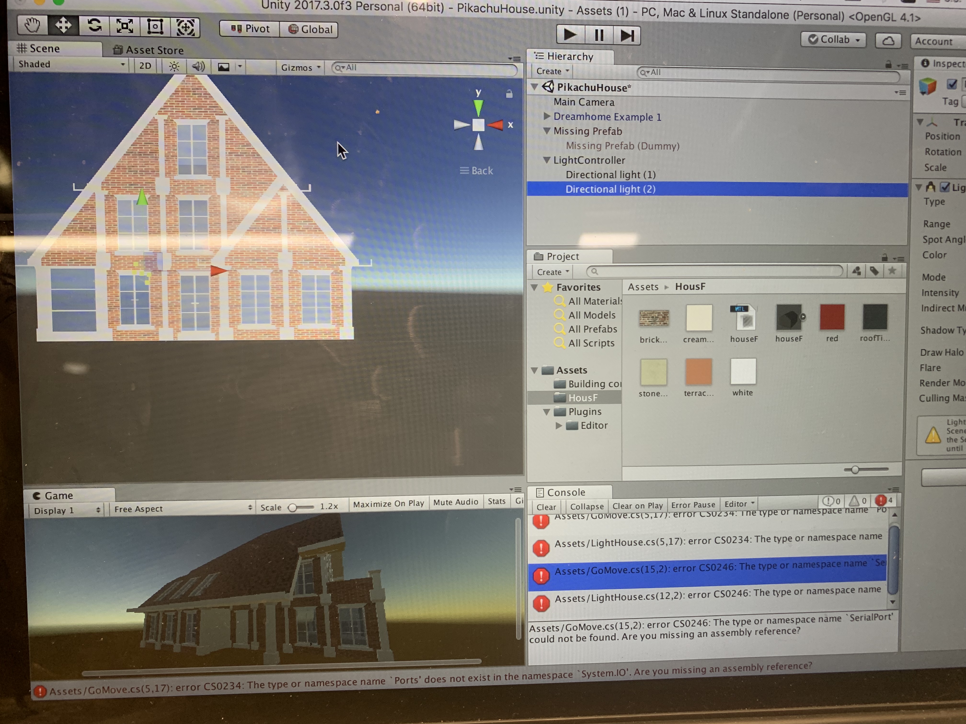
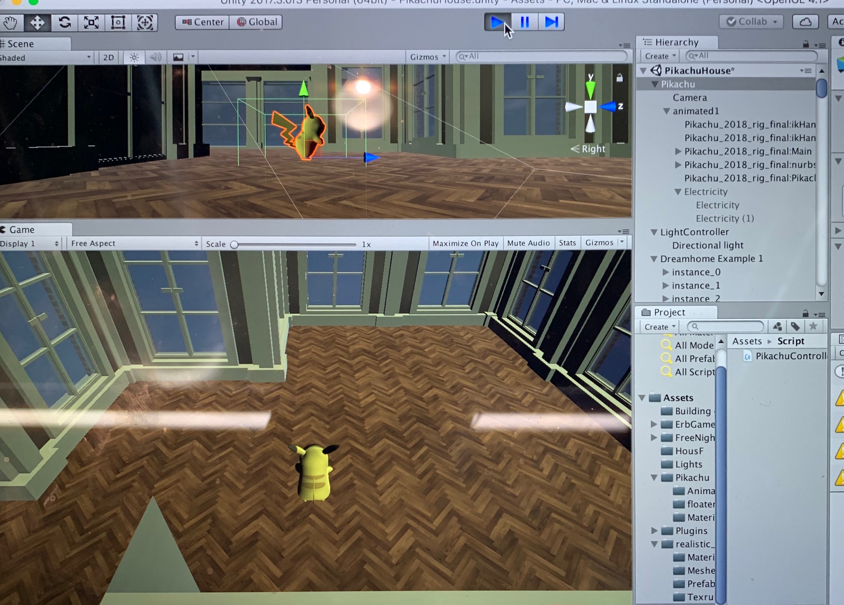
Step 4
Change the main object to the Pikachu 3D model
Step 5
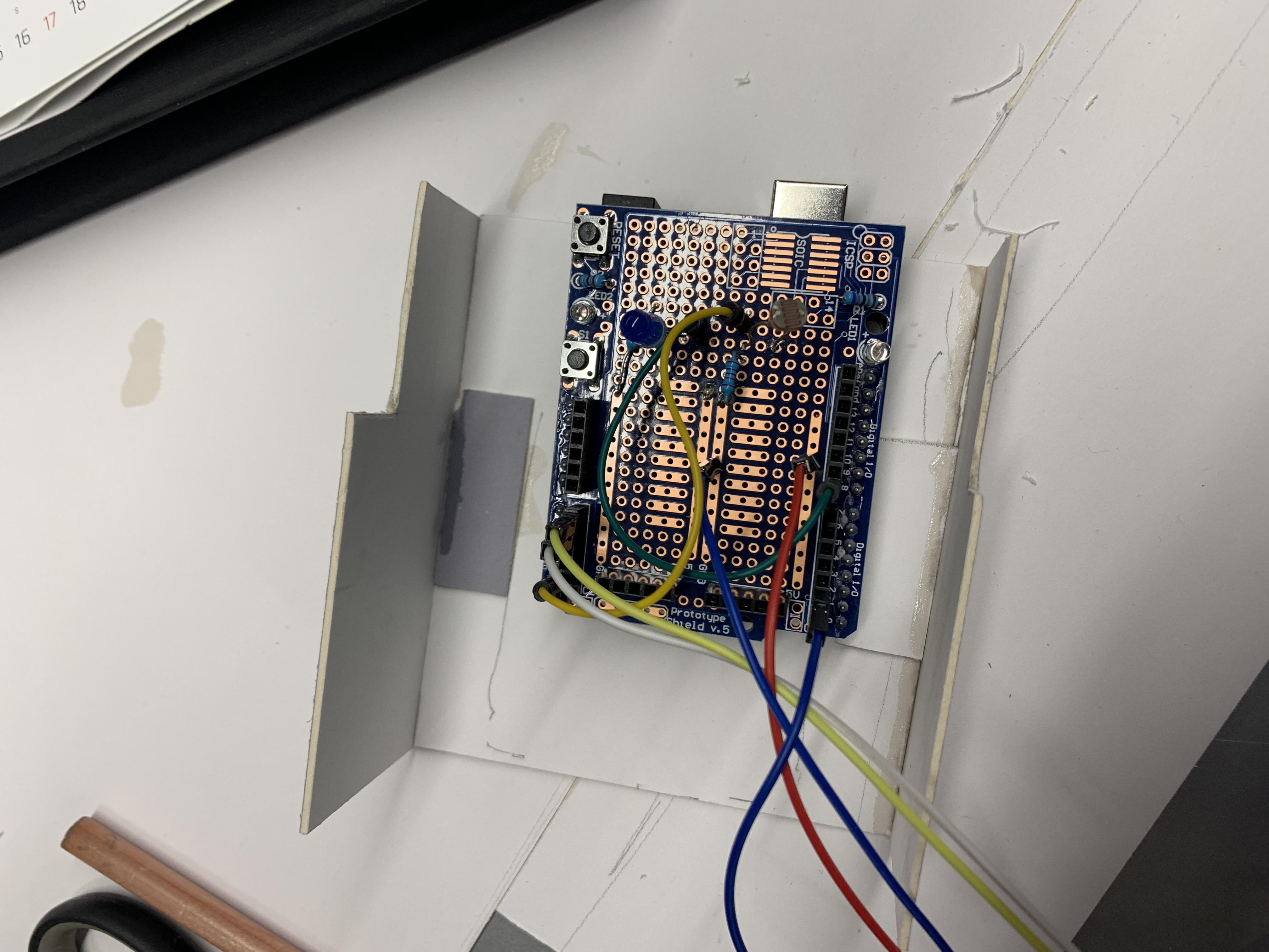
Soldering the wires
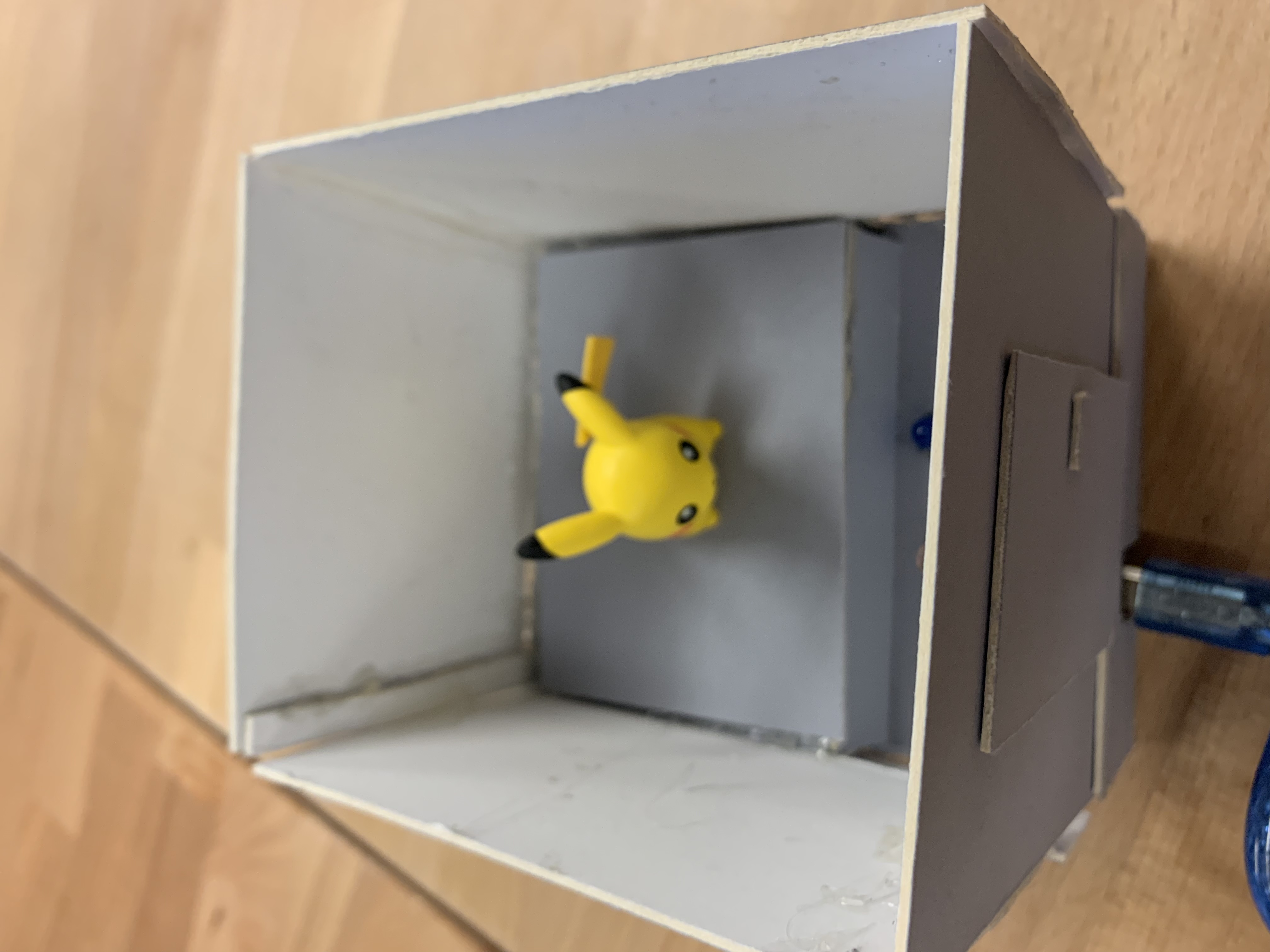
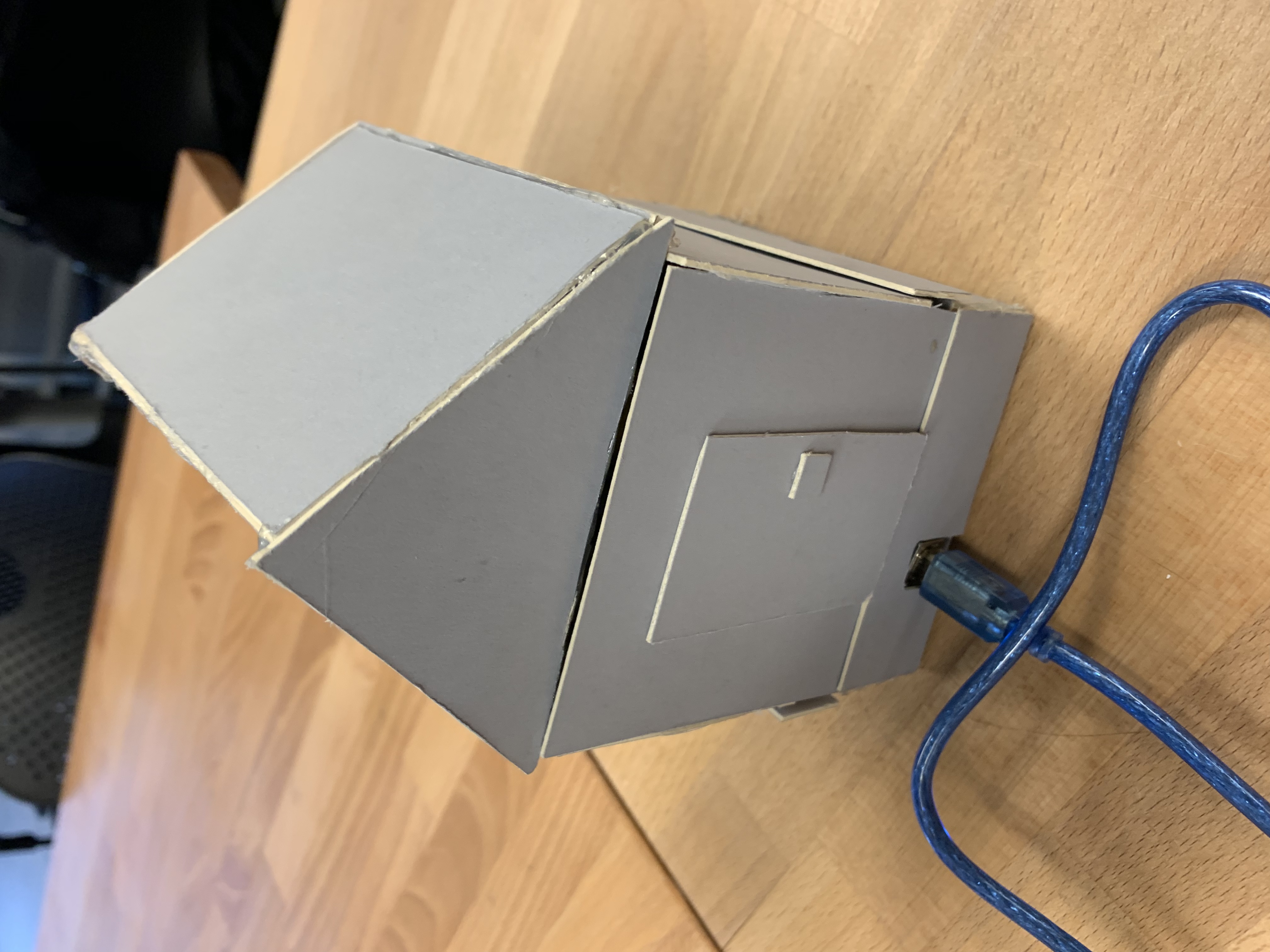
Step 6
Building the physical house for Pikachu
Thank you
Thank you for this quarter and have a nice spring break!