Assignment 7: Computer Control!
Geon Soo Park
Schematic
For Schematic I only drew 9 LEDs instead of 30 LEDs; to make the schematic simple
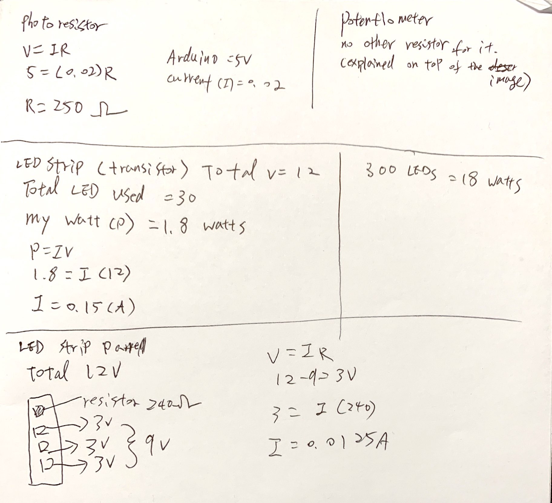
For the LEDs, I used 30 LEDs. Since 300 LEDs equal to 18 watts, 30 LEDs euqal to 1.8 watts. I used 12V for the power.
Therefore, by using the formula P = IV, we can find the current flow through the transistor. 1.8 = I(12), so I = 0.15A. Since the transistor can provide max of 0.6A of current, the circuit is safe.
For the resistor for base (connected to pin 5), I chose 10k ohms, because even without considering the voltage drop from the LED strip; R = P (12v)/I(o.o2A) which is 600 ohms. To secure my Arduino I chose 10k ohms for the resistor. I also calculated the current flow for each LED strip.
For the photoresistor, I used 10k resistor. The maximum current allowed to go into the ground pin is 200mA and I chose 5V for the power. R = V/I = 5v/0.02A = 250a. We need a resistor bigger than 250a. Furthermore, we need to use a resistor divider to allow the high impedence Anlog input to measure the voltage. We need to use the formula: Vout=Vin*(R2/(R1+R2)) to find the value for Vout. Vin is the 5V, R2 is 10k ohm, and R1 is the photoresistor (10k ohm).
For the potentiometer, I did not use any resistor because itself is like the resistor. The resistance value of a resistor stays the same until I change the resistance value of a potentiometer. Also, I did not use any external resistor because I did not use any LEDs connected to potentiometer.

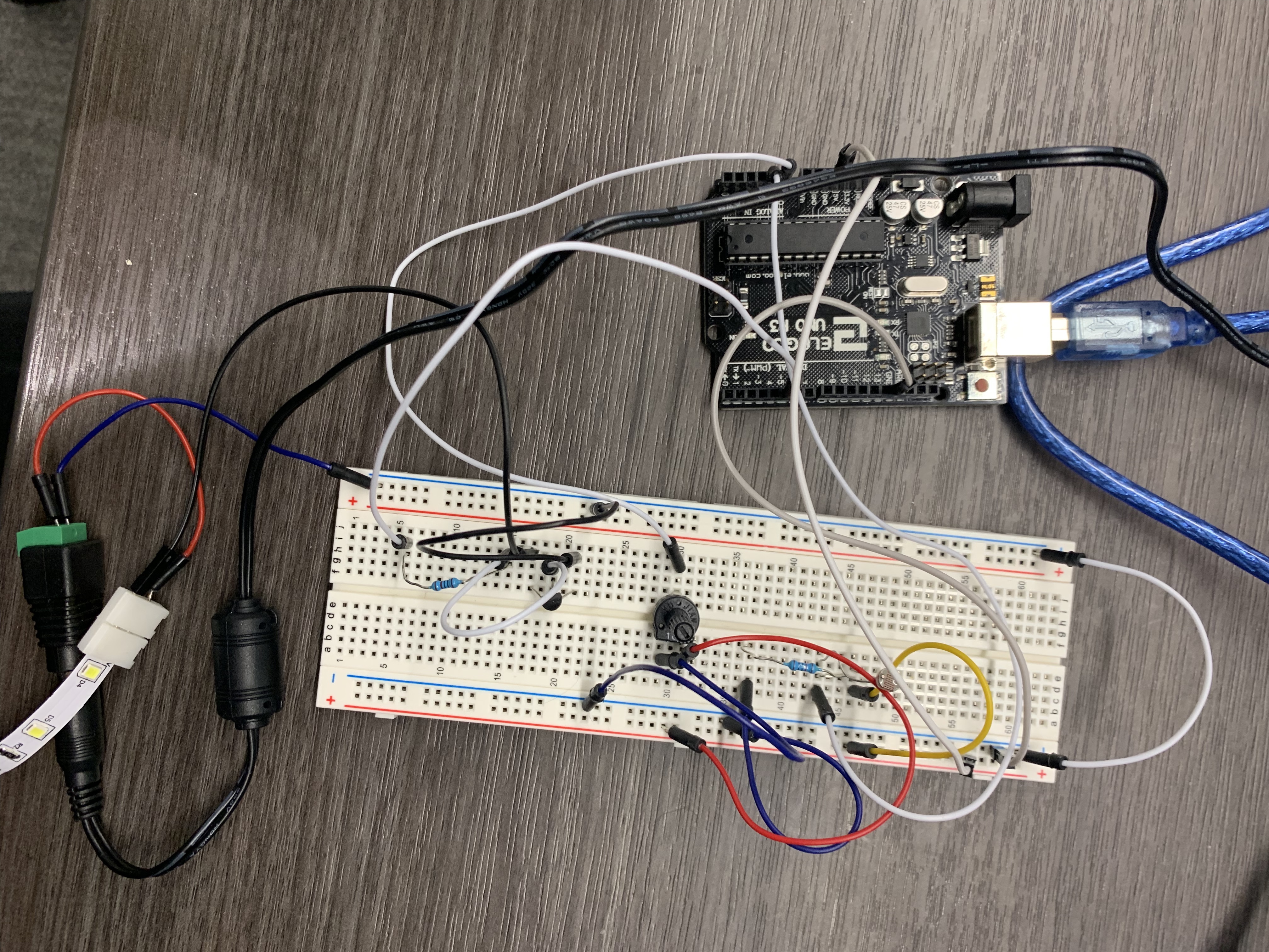
Circuit
The photoresistor is connected to the 5V and connected to the ground pin through a resistor. It is also connected to pin A0 which functions as a trigger the input for the photoresistor. The potentiometor is connected to the 5V, A1, and ground.
The positive side of power supply (12v) is connected to the positive side of LED strip and the negative side of the power supply (12v) is connected to the ground. The base of transistor is connected to pin 5 through a resistor, collector part of transistor is connected to the negative side of LED strip, and the emitter part of transistor is connected to the ground.

Firmware
Code 1 - Arduino
I set A0 as input, A1 as input, and pin 5 as output. int s1 and s2 tread the analog value from A0 and A1 pin. And I made serial print in the arduino [s1, s2] json data format and this format can be read on the web through p5. It delays 100ms. Belw, I made if serial is available, then it stores the serial value from webpage to int inByte. Then, it writes inByte value to serial, then it sends to LED strip through pin5.

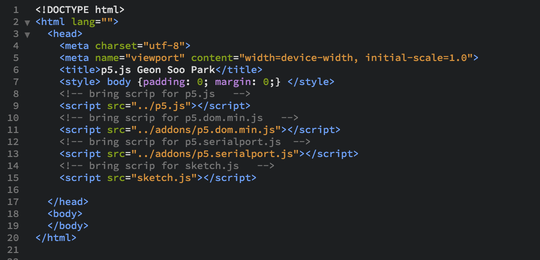
Code 2 - Index
This code is a html code for the interactive webpage. In the index.html, it reads four scripts: p5.js, p5.dom.min.js, p5.serialport.js, and sketch.js.
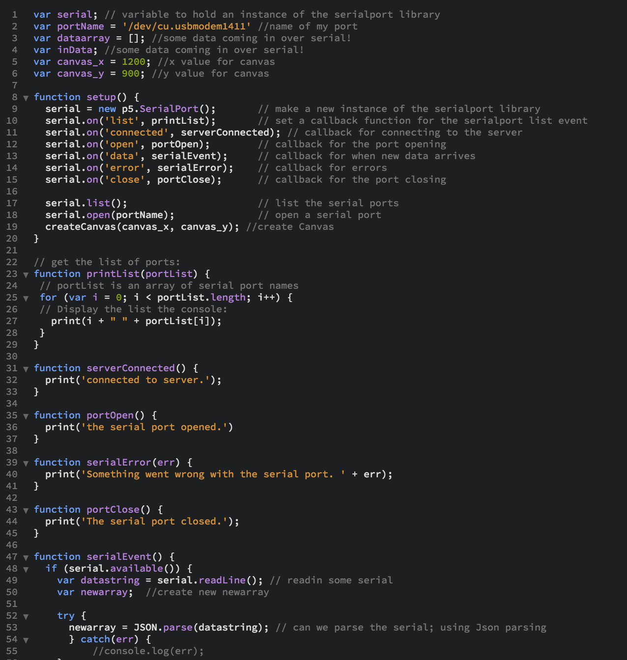
Code 3 - Sketch.js
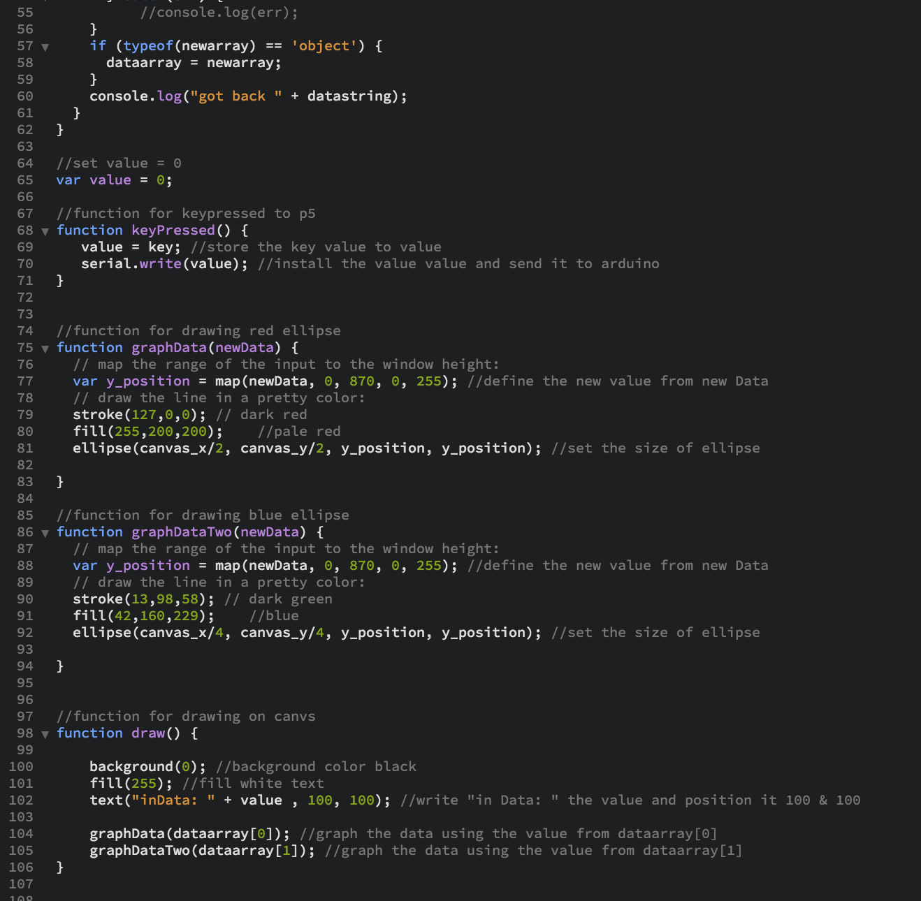
This is a sketch.js that gets and sends the data from/to the serialport library. I made two functions that draw two differents colors of ellipses. And I used a keypressed function so I can get the value from the keyboard typing. In the sketch.js I set the value for the x and y values for canvs size. In the code, it uses json parssing to read the data. In the graphData function, I used the map function to set the min and max (from 0 ~ 870) value for the graph. For the first ellipse function, I chose the stroke color to be dark red and ellipse color to be pale red. For the second ellipse function, I chose the stroke color to be dark green and ellipse color to be blue. Lastly, in the ellipse function, the x and y size should depend on the data value and the position should be one on the center and the other one on the leftside of the center on the canvas.
For the output function, I set value to be 0 and I used the keypressed function to store the key value to the set value. Then, I used serial.write function to write the value to arduino.
Lastly, I used draw graph function. The background of canvas in black, fill the text to be white and write "inData: " + value. Then, it draws two ellipses on the canvas.
Operation
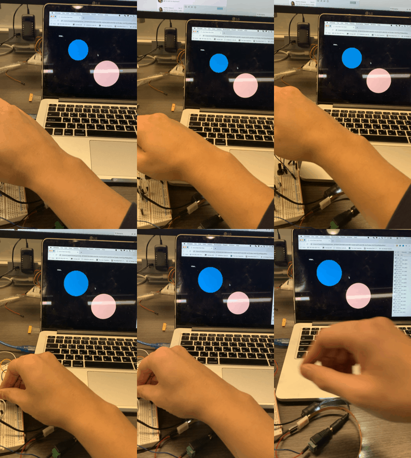
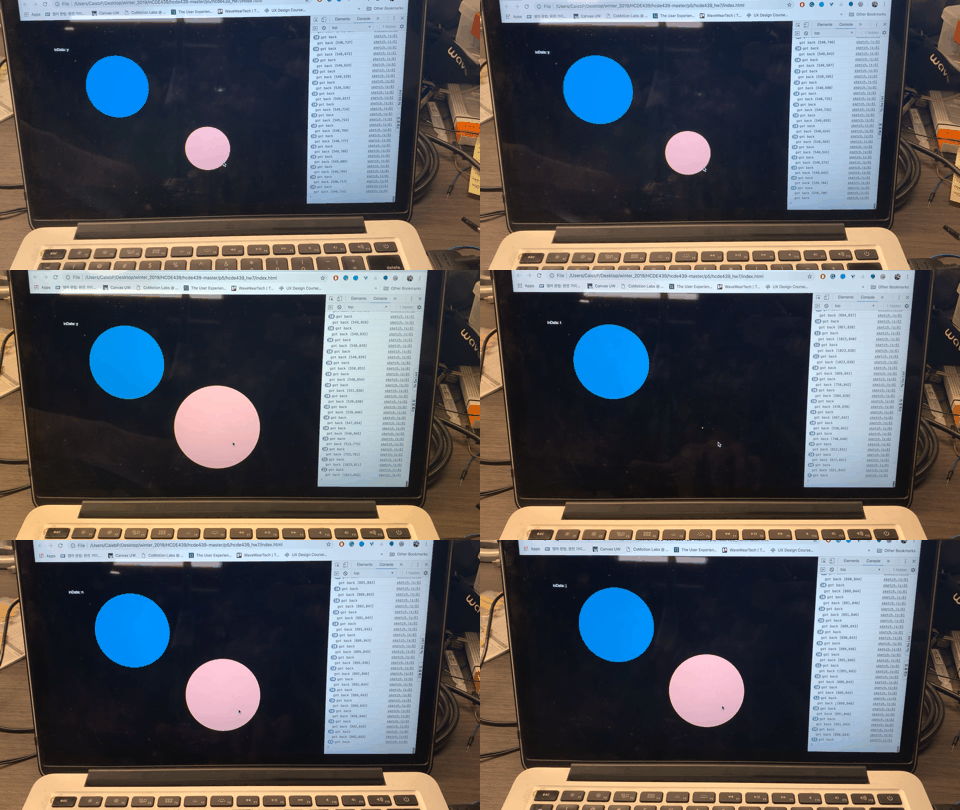
I made a webpage that interacts with the data from photoresistor and potentiometor. By using the sketch.js, I made two ellipses that changes the size by the data that it receives. Bigger the value, bigger the ellipses. Also, the website can displays the key I press. Then, the key value (according to this ascii table) sends to arduino. Then, LED strip changes the brightness of color depends on the value it receives from the keyboard. Bigger the value of key is brigther the LED light.

Thank you and have a nice day!