Assignment 2 - Lights that Fade!
Geon Soo Park
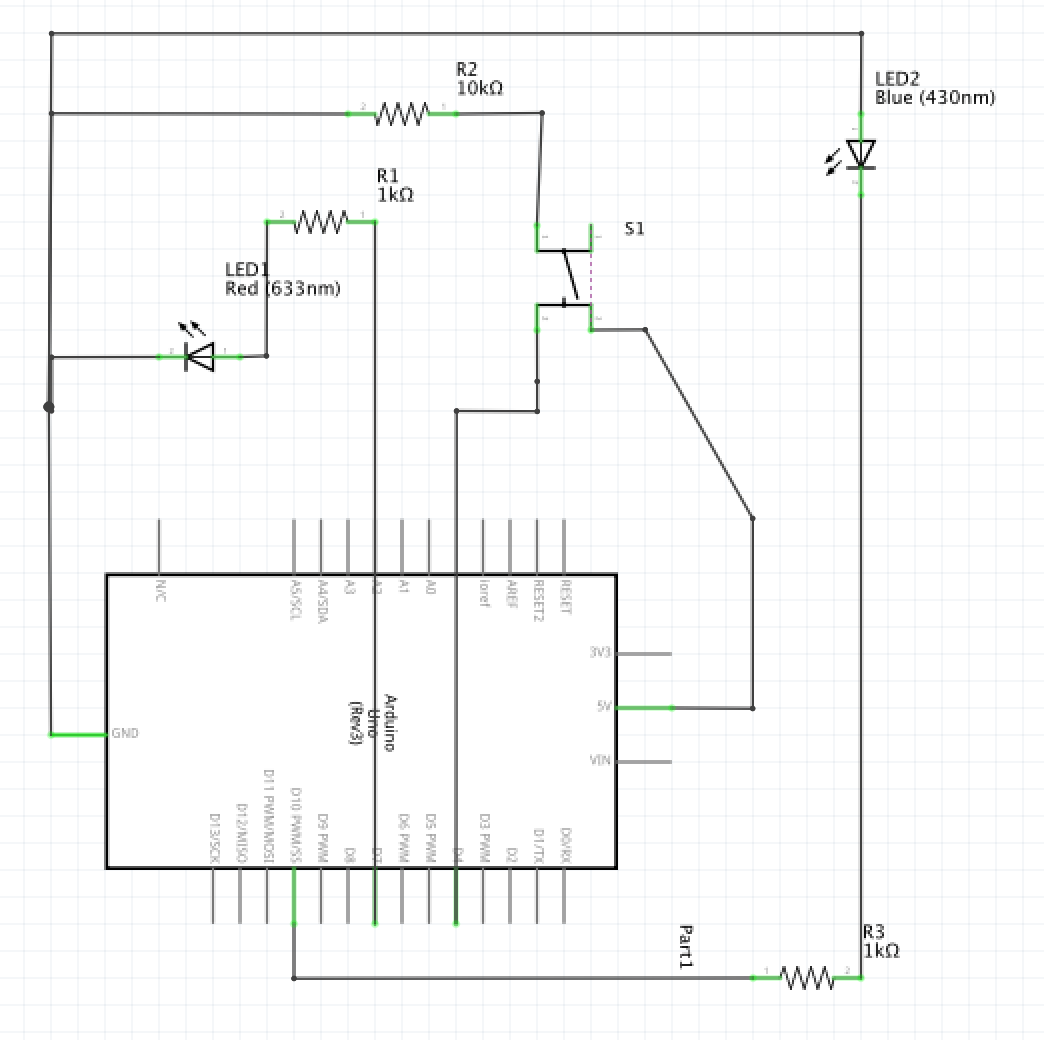
Schematic
I chose the value of 1k ohms for the red LED resistor. Because the volt from Pin 7 is 5V and the red LED has 1.8 V drop.
By using the Ohm's Law V = I * R: R = 3.2/0.02 which is 160 ohms, I found out that 1k would be a safe resistor for the red LED. I also chose 1k resistor for the blue LED. The voltage drop for blue LED is 3.3 V and by using the wOhm's Law which is 1.7/0.02 = 85 ohms; 1k resistor would be enough for the blue LED (if the ohms is higher than resistor then it will over burden the LED. If the resistor is too high then the flow of electricity is too low).
For the push button, I used 10k resistor. The maximum current allowed to go into the ground pin is 200mA and I chose 5V for the power. Therefore, if I do not use the resistor, it is same like connecting power directly to ground.
After using the Ohm's Law, 5/0.02, I need at leaste 250 ohms.
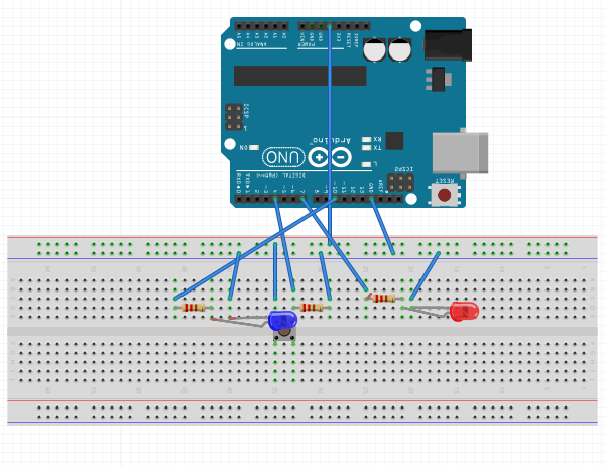
Circuit
The push button is connected to the 5V pin and connects to the ground pin through a resistor. It is also connected to pin 4 which
functions as a trigger (input and output) for the switch.
The blue LED is connected to pin 10 (because it requires analog format) through a resistor and connected to the ground pin. Lastly, the red LED is connected to Pin 7 through a resistor and then it connected to the ground pin.
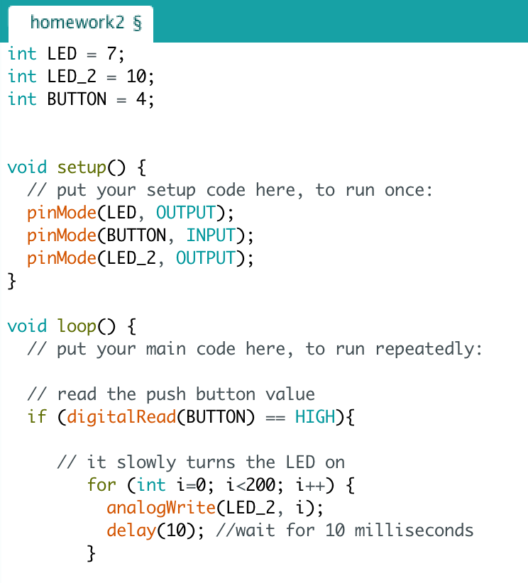
Firmware
Three integels are initiated (two for LEDs (#7 and #10) and one for the button (#4)). There are two outputs
from the Arduino board pin modes (#7 and 10) and one input for the button (#4). Once the user pushes the switch button then
it triggers the action for the code. The blue LED starts to fade in and waits for 10 milliseconds and to fade out for 10 milliseconds.
After that, the red LED starts to blinks in every 50 milliseconds. It blinks about 100 times in total.
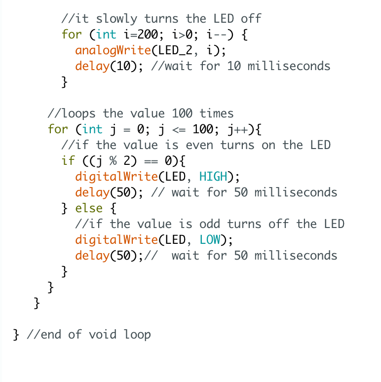
Operation
When the user pushes a button on the breadboard, the blue LED first start to fade in for 50 milliseconds and to fade out for 50 milliseconds.
After that, the red LED starts to repeatedly turn on and off (in every 10 milliseconds) for 100 times in total
Thank you and have a nice day!